Commando Kit
Commando Construction Notes, page 2
page 3
page 4
page 2: Commando Construction Notes
by Don Sebolt
Hi
Folks,
It is sunny but extremely cold. That means it was a great day to
work out in The Goat's Nest, the home of Old Goat Aviation. And
the work progresses thus:
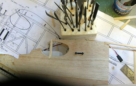
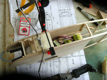
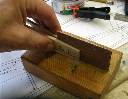
The electrical on/off switch is installed after checking clearances with the servo beneath. Both left side and top views are shown. Also show are all the different files that come in so handy when building a model. Cut small and file to a snug fit. He who has the most tools is least frustrated...
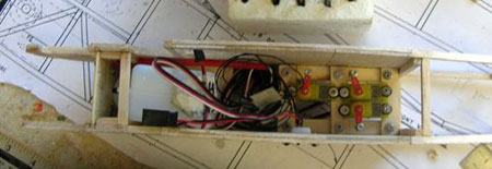
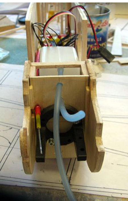
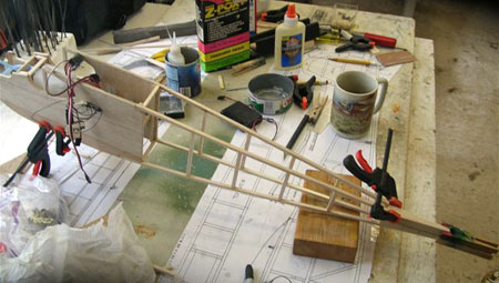
The gas tank with feed and pressure tubes installed. The throttle servo has been glued in with superglue and with epoxy resin and just clears the fuel tank.
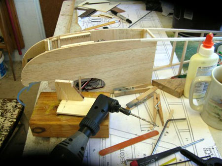
The landing gear cants forward at a 65 degree angle. A simple drilling guide was made out of thick balsa using a protractor.
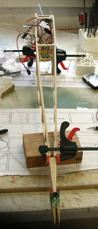
Landing gear mount is 1/8 plywood with a 1/8" plywood backer underneath. The mount is in its fuselage location and one side of the landing gear is being tried. Great Planes landing gear straps and screws will hold it in place. The angle of the gear can be fine-tuned using the drilling gauge to check the angle. If it's off, work the gear into the wood a little or file a little at a time.
Landing gear wires are bent, fitted into doubled 1/8" plywood, and the assembly fitted with clamps to the fuselage for drilling the Great Planes 1/8" nylon straps as shown. A Dremel tool is God's gift to modelers...don't stay home without one. I went from the 3/32" wire provided in the kit to 1/8" due to the size of the engine and other extra weight.
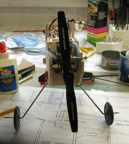
Frontal view with engine temporarily tried to check for clearance of 8-4 prop recommended as starting prop for .15 engine. The wheels are 2 1/4" Guillows wheels. Unless I can find some 2 1/2" narrow wheels, I will be using these. Since they are plastic halves, I will fill them with resin so they are less likely to pop apart on the stress of landing...some of us have more stress than others.
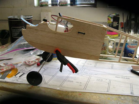
Side view showing the 65 degree forward cant achieved with the drilling jig.
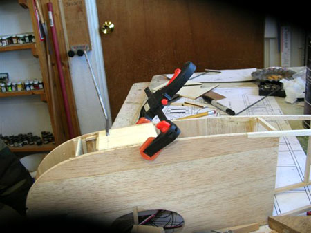
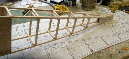
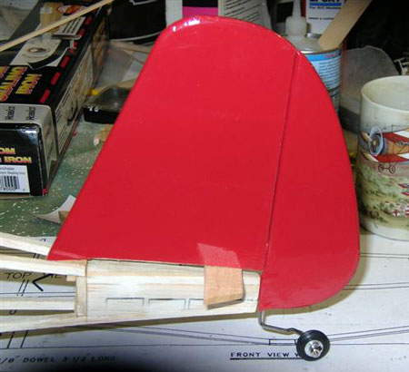
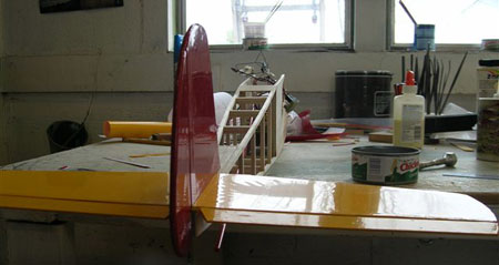
The tail is clamped and glued with the top filled in. It begins to look like an airplane.
A piece of plywood with medium grit sandpaper glued to both sides makes an excellent tool for tapering the inside of the tail. Normally another hand would be present moving the sanding tool back and forth...but I had to use that hand to snap the photo.
Rear view of the clamped tail after sanding to size.
I am adding top and bottom INSIDE cross braces to the fuselage behind the sheet cabin as they will greatly add strength to the structure by presenting a surface WITHOUT END GRAIN to the structure. End grain is a poor glue joint, and this model will be carrying more weight due to electronics and the large engine.
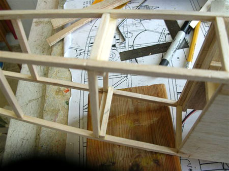
Bolstering of framework aft of cabin completed. These bolsters don't add much weight, but they really add to the strength of the frame.
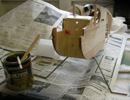
Balsa sheeting forward of landing gear and cabin have been added. The firewall has been sealed with a coat of polyurethane which is a great hot fuel proofer. Also a bit of the front of the fuselage and back to the end of the landing gear mount in case glo fuel somehow gets under the covering. Glow fuel wrecks plywood, glue, and balsa. Polyurethane also is good sealer to use where you will paint, like the cabin window area.
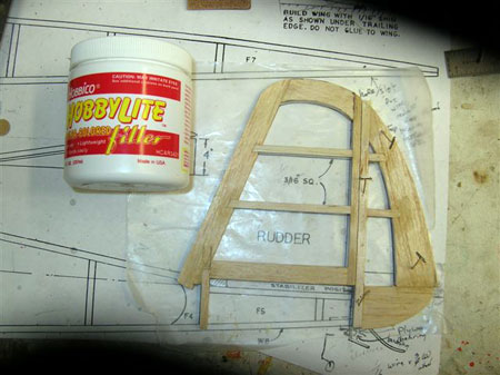
Next I got right with the program on the vertical stabilizer. I trace the outline of the redesigned and redrawn rudder out on paper. The vertical stabilizer and rudder parts are laid out before sanding on the belt sander. A belt sander does a great job of finishing out the roughed parts. You can sand right down to the lines with precision. Fine tuning can be done with a block or emery board.
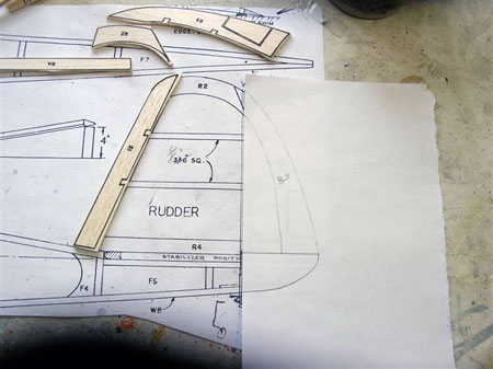
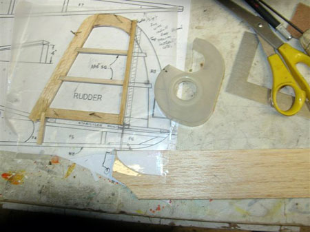
The vertical stabilizer is roughed out. Note the notch and the post inserted which will attach inside the fuselage giving more strength to the stabilizer. It was added due to the greater stresses demanded by a working rudder and will be much stronger than a flat glued joint. The bottom piece for the F-6 area traced on paper for the rudder bottom has been cut out and scotch-taped to the balsa flat stock. A scroll saw will cut right through it and the remainder immediately taken to the belt sand for sanding down to "the line". No need to glue it in place. First time I ever used this method, and it works just fine.
Vertical Stabilizer and rudder glued up and pinned in place. The Hobbico balsa filler has been used to fill in any gaps. After sanding, a drop of CA is recommended to harden it. It will also be used to fill in the pin holes.
The vertical stabilizer and rudder are joined and checked for clearances on the assembly. I use Great Plains CA hinges. The vertical stabilizer hinges are glued in, but not the rudder. The tailwheel wire with the tailwheel are shown below. A hole has been drilled halfway up from the rudder bottom piece and a slot made down the inside length for the wire to rest in using the same drill bit as a router tool.
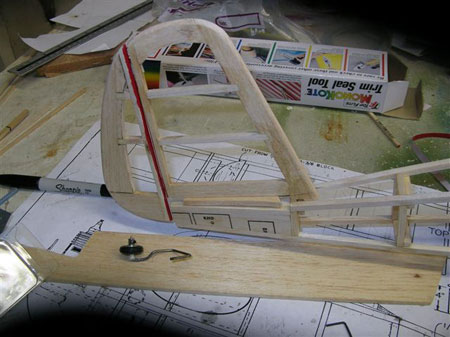
The tailwheel has been glued into the hole and slot using thin CA after again checking clearances. If you look close, you can see a fiberglass cloth wrap around to reinforce the assembly. The fiberglass cloth was also glued on with thin CA.
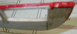
I go around the edges of tail and wing assemblies with Ultracote. I use low heat to activate the glue, but do not completely overlap to the flat surfaces. I then slit the remainder as needed to make it around the curves without wrinkles. The flats are done last. Lot less wrinkles this way. Being from the old school of using tissue paper, I'm new to using plastic heat shrink material. I use Ultracote as it seems to be more user-friendly. It's very workable and forgiving.
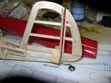
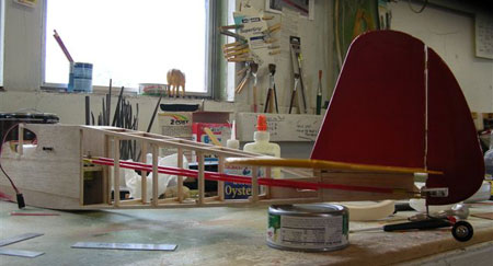
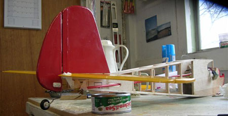
The completed fin assembly sitting in place prior to building the horizontal stabilizer.
The horizontal stabilizer has been framed up. Note the steel rule used to keep the 3/16 square trailing piece straight. It helps to have a straight trailing edge on a long wing or stabilizer, and you quickly find out how poorly an elevator or aileron fits if you do not do it this way. Sure works out the wrinkles. The elevators are shown below linked together with .074 wire in the shape of a U or staple. Holes were drilled in the elevators, a groove for the wire routed with the same drill bit, and the wire bent and inserted and CA'd in. I also added some 6 minute epoxy in the grooves and alongside the wire. It will hold well under stress. Next will come strips for hinges slotted and glued in with thin CA allowed to wick into the slots. The elevators are made from trailing edge stock, the leading edge of which measured 3/16 of an inch, same as the thickness of the stabilizer. All that needs to be done is to mark the center of the leading edge of the elevator and sand to a "V" shape, cover with Ultracote, and assemble.
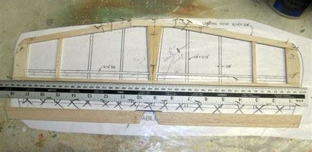
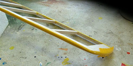
Photo is of horizontal stabilizer receiving edging of Ultracote. Sure cuts down on wrinkles this way.
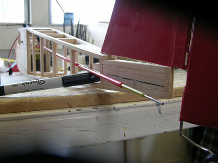
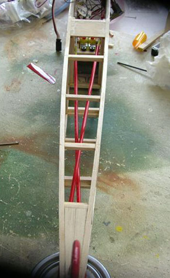
The elevator GOLD-N-ROD has been run from the servo and measured for length. Pushrod wire has been glued in, and the location of a control horn marked on the elevator. Exit location of the tubing has also been marked for a support piece.
A Kavan small control horn is located on the underside of the elevator and a mark made through one hole with an awl. After screwing to the backer, the other hole will be marked. Square keeps alignment. Kavan is a German company, and the small control horns have 5 holes (which needed to be drilled out larger) giving maximum adjustment to the throw of elevator or rudder. I got mine at the local hobby shop, but they have an internet address for those interested and unable to find any: www.kavanrc.com
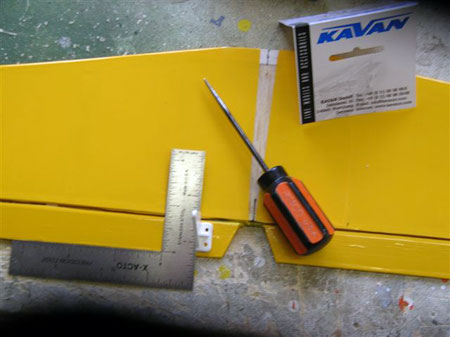
The run of the rudder tubing is established for marking the best location for a control horn on the rudder. The control horn must clear the elevator at it's full depression.
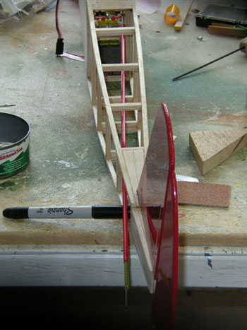
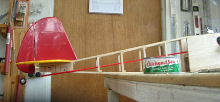
Both elevator and rudder tubing temporarily fitted and alignments rechecked. Notice the tuna cans and oyster cans? Shallow and deep cans are dandy implement or parts holders. Keeps the CA in a safe place so you can't be accused or being "stuck up". Tuna cans keep small parts together, at hand, and easily accessed. Like small plates and screws for control horns. I hate sweeping the floor for parts.

continued on page 3
back to page 1
forward to page 4