Commando Kit
Commando Construction Notes
page 3
page 4
Commando Construction Notes
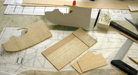
by Don SeboltThis how-to begins with a photo showing the start of two cabin halves wherein this Old Goat has come up with a "new" one...balsa plywood.
I have cross-laid 2 pieces of 3/32" balsa to form a "balsa plywood" cabin extending from the trailing edge of the wing forward. This plywood is then 3/16" thick and conforms to the original 3/16" square stock provided for the frame. I intend to work the frame into the solid cabin. I have an OS MAX .10 glow engine, and an OS MAX .15 engine for radio control. At this point, considering the same fiberglass engine mount will work for both, I'm putting in the .15 in the hope there won't be any hand-launching.
The photo contains one completed cabin side, cut out on scroll saw, one side being laminated, and the silhouette leaning against the carpenter's glue, is a thin-paper tracing of the cabin side taken from the plans, glued to very stiff cardboard, and then used to cut the shape of the cabin out of the laminated balsa.
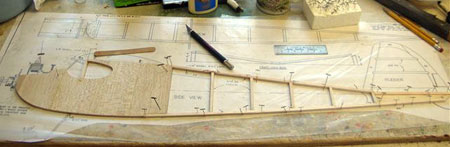
In the photo below, the model is pinned to the plan and is a bit out of order due to a camera/photographer malfunction. That's what happens to my planes when I fly...a mechanic/pilot error. HOWEVER...
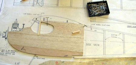
A pattern is traced to fill in the tail between the 3/16" square stock using 1/8" balsa rather than using F5 and F6 and 3/16" square stock from the kit. I intend to try to place a steerable tail wheel using the rudder, and this would be stronger construction using plywood at the base instead of balsa provided in the kit.
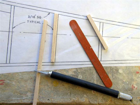
To duplicate the cabin sides exactly and blend to the 3/16" square stock aft of the trailing edge location, I made one cabin side's top and bottom cuts, marked the other side with a blade, not a pencil...then I used M'lady's emery board and clamps to make both sides of the cabin. Emery boards are a very handy tool for sanding...
Here is how I make the square stock exact. I use a blade, never a pencil. Fine woodworkers know that a pencil line will be off by its own width. A blade is much more exact. Make the first piece matched to the plans, then use the blade to mark the second piece from the first. Use the emery board to finish so both are EXACTLY IDENTICAL. Every time you're off a little on duplicate parts, it throws the symmetry of the whole work off that much. In the end, a crooked structure.
First fuselage side done. I used a combination of carpenter's glue and thin cyanoacrylate (CA or instant glue). I apply the CA using a plastic pipette used in laboratories.(Dave's note: you can get these applicator tips right here.) They're cheap, you heat the end with a match or lighter, extrude them to a super fine thinness, then cut them off with a fine blade. Keep 'em in a container upright, or find yourself glued to the table. It is wise to buy debonder, lest you become too "attached" to your airplane.
NEVER use CA glue where you have to sand. Use carpenter's glue instead. It sands well. Superglue doesn't sand worth a dang. I use a lot of CA in modeling, but I try to keep it away from outside surfaces. (Dave's note: "I used to think the same and then one of the guys in the Erie model club built a show model of the All American Senior using CA glue. I was amazed at how smooth he sanded the wood. I thought for sure he used white glue but then found out it was instant. He said the secret is to use a 400 or 600 grit paper on a sanding block to sand it smooth. It takes smaller bites but cuts through the instant glue with the rest.")
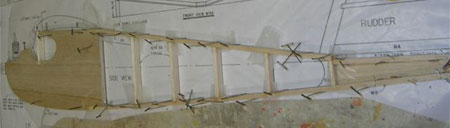
Here is a photo showing where the second fuselage side is being constructed OVER THE TOP OF THE FIRST to ensure perfect symmetry. The two sides are then exact duplicates of each other. I slip small pieces of waxed paper between the halves where glue must be applied to joints. Afterwards, I take the halves off the plan, match them with special care given that THE WING SUPPORTS ARE EXACTLY MATCHED and then sand any details that need it.
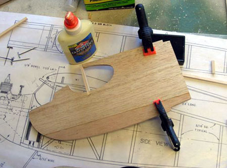
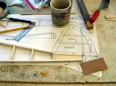
For the life of me, I could come up with no way to save the beautiful rudder and tail combo of the Commando and still get a working rudder and tailwheel. I had to saw off enough of the tail assembly to extend the rudder to where I could put a control horn on BELOW THE HORIZONTAL STABILIZER. Both halves were aligned and then sawed off as one unit, then sanded with the plywood with sandpaper glued to it shown...and that piece of plywood has medium grit sandpaper on BOTH sides of it. I will use it to sand the inside halves to mate them prior to gluing. You hold both pieces with the double sanding board in the middle and sand away until they mate perfectly. This should be done as the last step in assembling the fuselage halves when both sides have cross braces glued in and the whole is pinned or clamped to the top view to maintain symmetry.
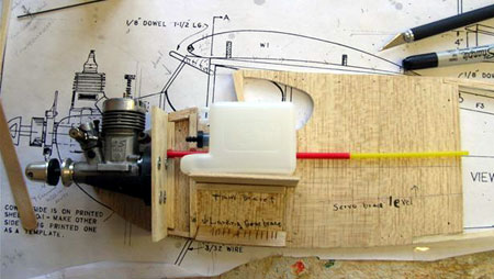
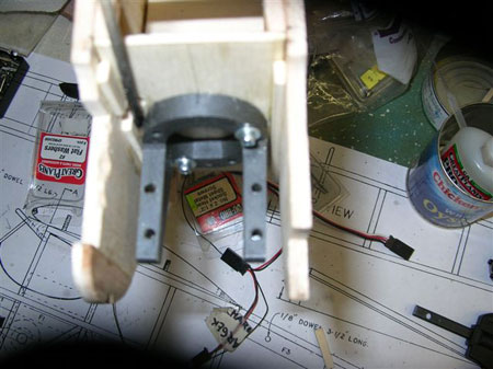
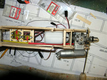
The plywood firewall is installed on the right fuselage side with braces behind it, the motor mount holes being pre-drilled and blind nuts installed and superglued. Photo shows the motor mount and OS MAX .15 engine in place so the hole for the throttle linkage could be drilled and temporarily fitted. The engine mount is a Dave Brown Products Motor Mount #1519. The control linkage is GOLD-N-ROD #504 Red-Yellow Flexible. The fuel tank and fuel tank floor are placed unglued temporarily to check the fit. The landing gear braces are 3/8" triangular balsa sawed through so they can be bent to conform to the plane's contours. 3/16" balsa will cover bottom in front of the landing gear, and 3/16" plywood will cover the bottom to install the landing gear where the triangular braces are located. A line has been struck to note the location and elevation needed for the servo supports and rails for throttle, rudder, and elevator.
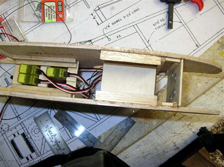
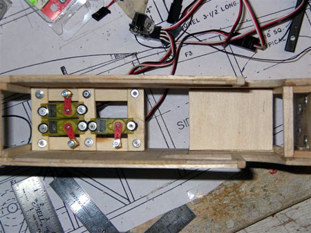
Two photos showing top and bottom views with rails installed for fuel tank and servos, with tank bottom and servos installed. Servos are screwed to rails with 2-56 socket head screws. The servos can then be removed individually or as a whole group. Tank will be installed with twist ties to facilitate removal/repair.
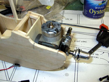
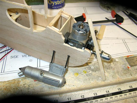
OS MAX .15 fitted to engine mount with access for needle valve cut out of left fuselage half, right fuselage half marked for cutting to install muffler. Note space between cabin and firewall fitted with recessed stock so sheet balsa can cover the space.
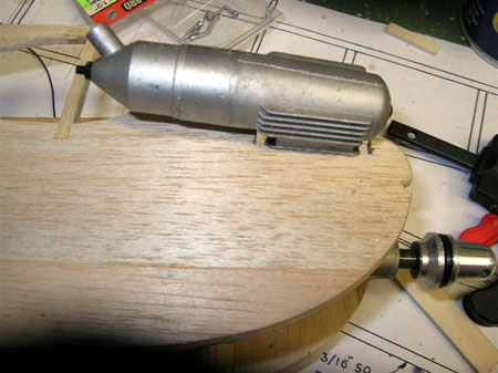
Right fuselage half cut for muffler installation. Note strip of 1/4" wide 1/8" thick balsa laying across front of engine that will be used to bolster front of engine mount.
Firewall front bolsters installed.
Muffler installed shows the fit is too tight. More stock will be removed to allow for clearance due to heat expansion/vibration.
Top view of muffler installation.
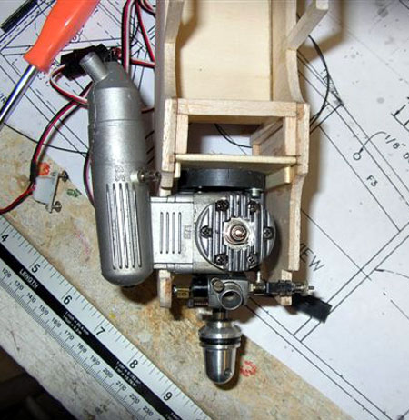
Top view showing fitting of engine throttle using #504 GOLD-N-ROD. Ball drive is shown placed in the set screw of the throttle's Great Planes pushrod connector. Access to the set screw necessitated filing a small crescent into the right fuselage front while moving the throttle to the farthest forward position. 2-56 threaded rod screwed into the yellow rod and attached to clevises are often displayed on these fittings, however I have found you can insert piano wire of the desired thickness into the yellow rod and then glue it in with thin cyanoacrylate (CA) glue. I have NEVER had one fail, and adjustments can be EASILY made to throttles. Only 1/2" need be glued into the yellow rod, thus giving maximum "flex" to the GOLD-N-ROD. Gets you through tight places and operates very smoothly.

continued on page 2
page 3
page 4