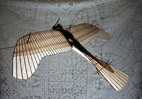
Etrich Taube Kit
Construction Notes for the Etrich Taube
by Malcolm Campbell
WINGS
Note :I would revise the plans to show a straight wing root frame and use the technique described below of adding a balsa block to be shaped to fit the resulting fuselage contour.
Measure and cut all ribs. Keep them in order as they are cut. (A simple way is to set them into pre-made rows of holes in a piece of plastic foam.)
Cover plan with wax paper or plastic wrap. Note: Do not use super glue with wax paper as it will soak through. It will also penetrate around pins to the plans even when using plastic wrap.
Place and pin the two 1/8" x 1/16" bottom spars to the plan per the Typical Wing Rib sketch (front spar is set on edge.)
Note: Rear spar is shown as 1/16" wide instead of 1/8" wide on plans. I set it with rear edge of spar and plan in alignment.
Wet the center of a length of 1/16" x 1/16" for the leading edge in warm water to facilitate bending and pin to plan, noting that it goes on top of the front spar. Cut and pin the other two perimeter pieces. (Crack the inboard piece behind the rear spar to facilitate alignment.)
Glue these 3 pieces together and to the spars.
Starting at the outer edge of the wing, place a rib so that it rests on the front spar and glue to the leading edge. Make sure it is aligned with the rib position on the plan and tight against the leading edge. Continue down the wing until all ribs are glued to the leading edge only.
After thorough drying, lightly score the top of each rib at the front of the front spar. Barely crack the rib by lifting it off the spar with tweezers forward of the score and bending the rear half down.
Put a drop of glue on the front and rear spars at the rib position and press the rear of the rib down in place. Hold, pin or weight down until dry.
When the ribs are thoroughly dry, place weights on the ribs (or pin) near the aft ends to assure that all are tight against the plan. Put a drop of glue on the end of each rib and attach a continuous length of heavy button thread the full length of the trailing edge. Make sure that there is no slack in the thread and that it is pushed down to the bottom of each rib.
When dry, (BEFORE REMOVING FROM THE PLANS), use a small sanding block to taper the aft tip of each rib down to the thickness of the thread.
Remove wing from plan. Round leading edge and taper end of front spar as shown. (Don’t taper to a point; leave flat for the rigging to glue to.) Run a small bead of glue over the thread on the trailing edge to stiffen it. When dry, turn the wing over and align with plan for opposite wing. Mark the location of the line where the covering will end on the bottom side. Glue a piece of 1/32 x 1/16 to the underside of the ribs (3rd spar), following this line. (The 1/16" face is glued down and the strip extends forward from the line.) Trim excess glue on the entire wing when dry.
Make a jig by contouring the end of a piece of 1x6 pine about 2" long to the shape of the wing root contour drawn on the fuselage side view. Soak the wing in water for at least 15 minutes and put a shallow notch with your finger nail at 3 or 4 places on the bottom of the first 6 ribs between the leading edge and the spar. Pin the trailing edge of the wing root to the trailing edge of the jig and ease the leading edge down to conform with the jig. Pin in place and dry over night. Remove from the jig.
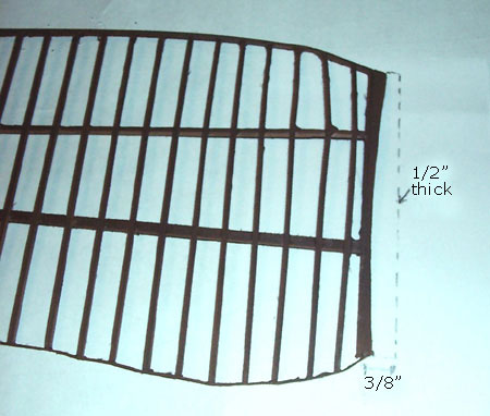
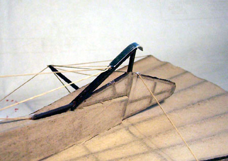
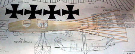
Cut a piece of balsa approximately ½" x 3/8" and glue the ½" face to the wing root as an extension. Sand to the shape of the wing cord contour both top and bottom. The end will be contoured to fit the fuselage when the wings are installed. See photo.
The wing is now ready for covering.
The top of the wing is completely covered, the bottom back only as far as the rear edge of the 3rd spar. However, for ease of covering, the bottom may be completely covered. If a rigid covering is used (tissue with several layers of enamel) it is OK to attach the covering to just the perimeter of the wing. If a flexible covering will be used (unpainted or lightly painted tissue), attach covering to all ribs and spars to provide a more rigid structure for rigging attachment. If light covering is attached to just the perimeter, it will be necessary to penetrate the covering to secure the rigging.
When working on the rigging and the gear, it is helpful to rest the model on a piece of egg crate foam to help prevent damage to the rudders, rigging posts, etc and to keep it from moving around.
The Engine
I just cut 6 pieces of 1/4" dowel, glued them together, sanded one end flush and the other to match the cowl. Then I drilled holes in the tops of the cylinders and inserted pre-cut and pre-bent lengths of #8 copper wire for the exhaust stacks. The intake and manifold are pieces of my old standby, heat shrink tubing.
RUDDER
Build per plan except leave out the skid member on the lower rudder. Fabricate a skid from a piece of 1/8" x 1/16" balsa. Carefully file a 1/16" notch down the center of one end far enough to slide the skid over the bottom of the lower rudder to the fuselage after the rudder is assembled to the fuselage. Trim the length so that it fits against the bottom of the vertical strut on the rudder. Cut a piece of thin aluminum or brass 1/8" wide and ¾" long. Bend a curve as shown about ¼" from the end and glue to the lower side of the skid strut. Install the skid after the rudder is installed.
Cover both rudders.
STABILIZER
Build per plans but leave the rigging extensions off the rear spar. (They are fragile and interfere with covering and assembly.) Taper the extensions and glue on after stabilizer installation and covering.
Follow the wing instructions for adding thread to the trailing edge, tapering the ribs and stiffening the thread with glue. Do not cover the stabilizer before installing on the fuselage.
FUSELAGE
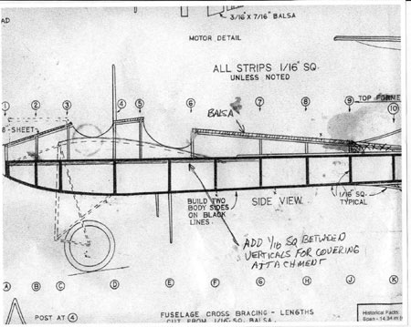
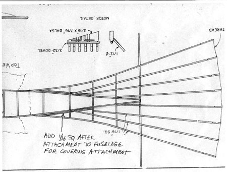
It is important that the two sides be identical. To aide in this, place a row of pins on the outside edges of the top and bottom black lines of the fuselage sides close to each vertical brace. Use these to position the top and bottom balsa and insert and glue the vertical pieces, cutting them long enough to force the sides against the pins. Add a second piece of 1/16" x 1/16" to the bottom of the top rail between the verticals starting at the front and ending at Station G. These provide a surface to attach the covering to. See drawing below.
DO NOT REMOVE THE OUTSIDE PINS TO REMOVE THE FIRST SIDE FROM THE PLANS. Build the second side the same way against the same pins.
When both sides are dry, pin them sitting upright to the top view of the fuselage and glue them together at the aft end. Using the lengths on the plans as guides, cut the top cross braces a little long and individually trim them to fit between the two halves. Glue as they are installed. Cut the bottom cross braces to the exact lengths shown on the plans and install and glue each in place.
Cut each of the formers at least 1/16" larger than the printed outline all the way around. Sand each down to properly fit between the fuselage halves at the indicated locations. Add stringers as indicated.
Cover the top of the fuselage with 1/16" balsa as far as the rear of the rear cockpit. Make a paper template for the cockpit openings and cut them exactly the same on both sides so that the wings can be installed at the same place on both sides.
Note: The balsa covering can be carried back to F9 but only after the stabilizer has been installed. In this case, eliminate F10, and terminate the top stringer at F9. After adding the balsa covering, carve a tapered balsa cap to finish off behind F9. It is also then necessary to add a piece to the bottom of the top rudder to raise it to the original top stringer location. 1/16" filler strips for the tissue to attach to have to be added to the spaces where the top of the stabilizer contacts the fuselage.
Do not install the rigging post to the fuselage (1 on top, 2 on bottom) until ready to install the rigging.
Glue the stabilizer to the fuselage.
FIT THE WINGS TO THE FUSELAGE (BUT DO NOT INSTALL) BEFORE COVERING THE FUSELAGE
FITTING THE WINGS
Using a paper template, draw a line indicating the position of the top of the wing on each side of the fuselage. (The front spars line up with F4). Make sure the positions are identical. Securely tape and/or pin the fuselage down to a flat surface covered with a writing surface. Draw straight lines out from the fuselage representing the positions of the front spars (not the leading edges.) Make sure they are square with the fuselage and form a straight line. Set an 1-1/2" high block at the end of each line approximately where the tips of the spar extensions will fall. (With the wings properly installed, the tips of the extension will be 1-1/2" above the bottom of the fuselage.) Using the lines on the fuselage to position the wing root and the drawn lines and blocks to position the tips, carefully carve and sand the wing root balsa extensions to conform to the fuselage. Constantly check the alignment as you go.
FINISHING THE FUSELAGE
Once the wings are fit, the fuselage/stabilizer assembly can be covered. After covering the fuselage, add and shape the nose block.
Install the upper rudder (only).
INSTALLING WINGS
(I suggest that the wings and fuselage/stabilizer/rudder be painted before the wings are installed.)
Securely reposition the fuselage to the surface used to fit the wings. Stick small pieces of clay on the fuselage at the positions of the forward and aft lower wing surfaces. Adjust until the wing is in the proper position when resting on the clay and on the block at the tip of the spar extension. Lift wing off, coat the mating surface with glue and put back in place. Remove the clay after the glue has dried.
DO NOT DISTURB THE ASSEMBLY UNTIL THE WING BRACING HAS BEEN INSTALLED.
INSTALLING WING BRACING
The vertical braces attach to the bottom of the front spar under the indicated ribs.
Cut the horizontal brace a little longer than shown on the plans. Cut the 3 verticals per the plan. Attach the horizontal to the lower edge of the fuselage below F4 (Position not now indicated) with glue and prop into approximate position until the glue is dry enough to keep it from falling off. Put glue on both ends of the outer vertical and attach it to the spar at the appropriate rib. Bring the horizontal brace into contact with it and adjust the point of contact so that the vertical brace is square with the wing. Allow this assembly to thoroughly dry then add the two other verticals. Trim the outboard end of the horizontal if necessary. Repeat on the other wing.
Remove assembly from the board and turn upside down. Add rigging wires as shown across the two inboard vertical braces on each wing to stabilize the wings. Attach the rigging at the rear spar, stretch across the brace and attach at the front spar. When the glue is dry, make sure the bracing is square with the fuselage and glue the rigging to it.
Install lower rudder, skid, rigging posts on stabilizer, rigging posts on wings and rigging posts on fuselage as shown.
LANDING GEAR
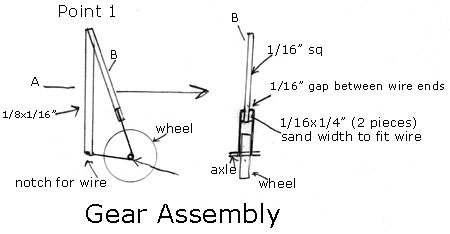
Make two identical wire wheel mounts as shown. Each wire is a single piece with the open ends at the top. Trim the open ends to a gap of 1/16". Install the wheels to the axle using the spacing shown. Support the axle at the middle with the wheels off the bench and hang the wire mounts upside down over the wheels and axle. Glue to axle.
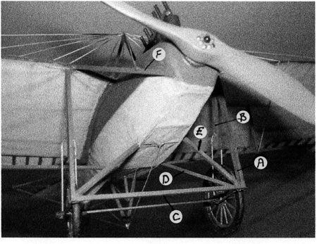
Make pieces A and B per the drawing and make up the Gear Assembly shown. Add strut C between the pieces A.
Turn the model upside down and glue Points 1 of the Gear Assembly to the leading edge of the wings. Support the assembly so that strut A is close to square with the fuselage. Before the glue completely dries, cut struts E to a length which will provide the slightly forward angle of A shown on the plan side view and glue in place.
Fit and install struts E and F.
RIGGING
Install all rigging as shown on plans. (Show extra line from post under fuselage forward to stabilize it.) Not all rigging points are marked on plans.
Note: Instead of using fine thread and pulling through with a needle (hard to go through the ribs safely), I used heavy thread surface mounted. I put a drop of glue on the surface, stuck the thread into it, dried it with the heat gun, then pulled it over the post, added a little glue and held it taunt while I dried it with the gun. I actually attached one end of many lines, then pulled them and attached the other end in a sequence that tended to keep the tensions balanced so that I didn’t slacken them once installed. I didn’t use the branching shown on the wings and tail — all lines were run to the posts so that I could control the tension.
FINISHING UP
Fabricate and install the motor and prop.