Bristol Beaufighter Kit
Bristol Beaufighter Construction Notes
FUSELAGE
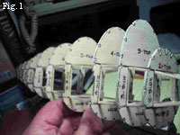
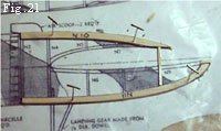
The vertical orientations of the fuselage side formers are not indicated. On formers 4, 5, and 6, the second notch, which accommodates fairing #16, is toward the top. On all others, the single stringer notch is closest to the bottom. (Fig. 1.)
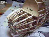
There are short, curved parts similar to #15 (on the cowl) identified as 5 and 14. I used the 5s next to 15s on the cowl (they are identical to 15) but found no need for the 14s. There are two pieces needed to complete the cowl shape (on either side of the 5s) but the 14s aren't right for that so you have to make these. Fig. 2 shows them before shaping.
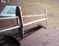
Also note (Fig. 3) the extended vertical at the end of the fuselage where the stringers terminate. This extends 3/8" above and below the frame.
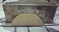
The instrument panel needs to be reshaped to fit the wind-shield provided. (Fig. 4.)
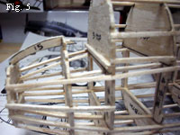
I added a 1/16" sq support for the panel to make it easier to position it as shown in Fig. 5.
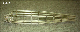
It can be seen in Fig. 2 that I left the front edge of the instrument panel about 1/32" above the surface of the cowl so that the canopy could be positioned against it. Fig. 6 is a photo of the completed fuselage structure less the wing fairings (#15 & #16.) These pieces are not included in the printed pieces and have to be cut from outlines included on plans. Do not install 15 and 16 or cover the fuselage until the wings are built and ready to be fit.
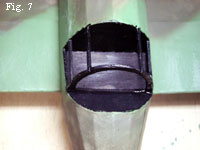
I also later cut the center out of the top of F-3 and added a floor between F-3 and F-4 to stylize the cockpit as shown in Fig. 7. Add and shape the nose and sand the fuselage as necessary.
WINGS
The plans call for 1/16" sq spars but the ribs are printed for 1/16" x 5/32" spars. As can be seen in the construction photos, I used 1/16" sq. After covering and sealing, I discovered that the spans were too long for the 1/16" sq to support the tissue shrinkage without bowing. I had to later remove some covering and reinforce the spars in several areas to get rid of the bow. USE 1/16" x 1/8" SPARS which have been added to the kit.
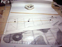
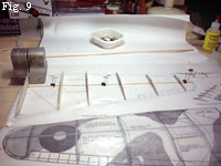
Build the wings flat on the bottom spar, installing the ribs, then the top spar. (Figs. 8 & 9.)
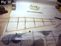
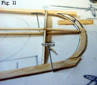
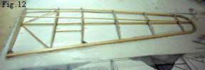
Trim the ends of the ribs and pin the trailing edges of the ribs to the plans. Install the trailing edge. Install the leading edge from inboard to the middle of R-3, then another piece from there to the tip. (Fig 10). Block the leading edge of the tip up 1/16" and install the tip pieces. (Fig. 11). Add the internal wing supports and fillets. It was not clear on the plans where the internal supports were to be attached. I ran them from the bottom spar to the trailing and leading edges. (Fig. 12).
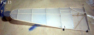
Now, notch the top of the leading and trailing edges and top spar at the out-board edge of W-3. Cut the bottom spar clear through at the outboard edge of W-3. Pin the trailing edge down from W-1 to W-3 and lift the tip 1-7/16". Block at this height. Add a piece of scrap to fill the gap created in the bottom spar. Apply glue there and to the notches in the leading and trailing edges and the top spar. I don't have a photo of this, but Fig. 13 recreates the configuration with part of the covering on. Taper the edges and tips. Blend the tips of the ribs into the edges. Do not cover at this point.
FITTING the WINGS (Preliminary)
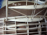
To assure that both wings are positioned the same, install the fairings (#14 & #15) around them rather than installing the fairings first. Start by making sure the notches in F-4, 5, & 6 are such that the wing can be inserted in them and the forward tip of W-1 positioned ¼" from the rear of F-9. If not, open the notches as necessary.
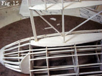
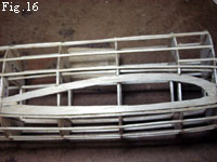
Then extend the notches in the lower portions of these 3 formers to allow fairing #15 to sit flush with the stringer below it. (Do not install #15 at this time.) Position the wing and pin in place as shown in Fig. 14. Shape #16 so that it fits snugly between the top of W-1 and the upper notch in the formers. Glue in place. (Fig. 15) BE CAREFUL TO NOT GLUE THE WING. Remove the wing and shape the lower edge of #15 to fit to the stringer below the wing notch and glue in place (Fig. 16). Do not fit #15 to the wing at this time. The fuselage can be covered at this point. Wait to cover the wings until the nacelles are fitted.
NACELLES
These are tricky to build true to shape, which is important since the fit to the wing is critical. After several tries, I had success with the following procedure.
NOTE: Observe the “bottom” notation on the two halves of N-4 when assembling them. (The printed sides have to be reversed.)
To begin with, fill in the centers of N-1 & N-2 with a circle of 1/16" or don't cut the centers out and patch where they overlapped on the printed sheet.
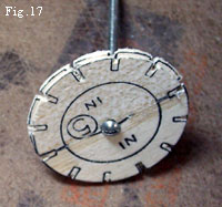
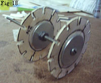
Locate the centers of these and drill a 1/8" hole in each. Thread a #6 machine screw through N-1 & N-2, hold them together and cut the notches so that they match (Fig. 17.). Using a long #6 machine screw, 3 nuts and 4 washers, space the two formers per the plans (Fig. 18).
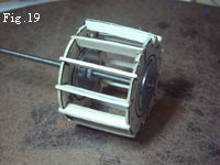
Install 12 #12s, adjusting the notches if necessary so that each parallels the center screw. (Fig. 19). Remove the screw and sand the ends of the #12s flush with the formers. Roughly shape the outer edges.
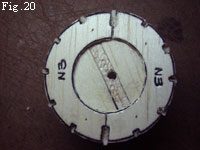
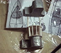
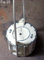
Cut the notches in N-3 to match those in N-2 and glue to the back of N-2. (Fig. 20). Pin N-10 & N-11 to the plan. Add a piece of 1/16 sq glued between them at N-9. Add a piece of 1/16 sq to the end of N-11 to extend it vertically 1/16" (Fig. 21.) Mark the positions of N-4 through N-9 on the top of N-10 and the bottom of N-11. Fold the plan over a square edge at the rear edge of N-3. Glue the N-1 — N-3 assembly to N-10 & N-11 making sure the pieces are square. (Fig. 22) Add a gusset between N-10 and N-3. When dry, remove from plans and add a gusset between N-11 and N-3. You now have a good, stable backbone for the rest of the construction. (Fig. 23).
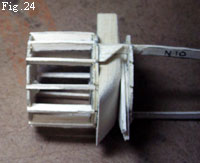
Making sure that it is properly orientated top and bottom, slide N-4 over N-10 and N-11 and use scrap to space it the proper distance from N-3 and to keep it parallel to N-3. (Fig.24). Glue in place. Remove the spacer. Add the remaining formers at the positions previously marked. Make sure they are perpendicular to N-10 and N-11. Remove the support at N-9 before adding N-9.
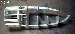
Install the two short stringers between N-3 and N-4 at the wing tip positions and the forward half of the two just above those. (Fig. 25). The second halves of these are installed after N-13 and N-14.
NOTE THAT N-13 AND N-14 ARE REVERSE-IDENTIFIED ON THE PLANS.
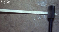
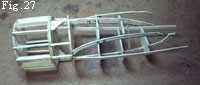
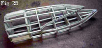
Wet and pre-form the bends in N-13 and N-14. (I rolled the inside surfaces with a rotary cutter prior to wetting to make them easier to bend.) (Fig. 26). Glue N-13 and N-14 to N-4 and N-5/6 on both sides. (Fig. 27). Pinch the ends of the two N-13s against the tip of N-10 and glue there and to the remaining formers. Do the same (but on N-11) with the two N-14s. Both of the N-13s and 14s may have to be trimmed at the ends so that they meet at N-10⁄11. Do this before gluing. Install the rest of the stringers. (Fig. 28).
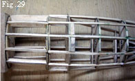
On each cowl, add a piece of 1/8" x 1/4" balsa on the rear side of N-3 on either side of the spar. (Fig. 29.) Sand to blend with N-3. This provides material in which to mount the gear later.
Sand the stringers flush with the front of W-1 and add the cowl block. Shape the cowl and smooth the nacelle as necessary. The nacelles can be covered at this point.
FITTING the NACELLES
Temporarily, cover the tops and bottoms of the W-2 — W-3 bays on the wings with bond paper. This provides a fairly rigid surface to fit the nacelles to. Slide the nacelle on the wing from the tip. Sand or carve N-13 and N-14 as necessary to get them over W-3 and into position on the bay. Note any significant gaps between the nacelle and the wing covering and glue small pieces of 1/16 to N-13 or N-14 at these locations. Sand or carve to make a good fit. Remove the paper covering. The wings may be covered at this point.
VERTICAL STABILIZER
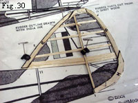
Add 1/16" x 3/16" pieces to bottom of stabilizer frame to provide attachment for the horizontals. (Fig. 30.)
WING FITTING (Final)
After the wings are covered and painted, trim the upper edge of fairing #15 to allow the wing to slide freely in place. Some re-shaping of #16 may also be necessary to accommodate the finished wing.
GEAR
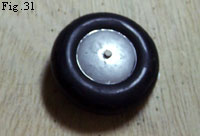
Start the main gear by assembling the wheels and inserting a piece of 1/12" dowel for the axle. Trim so that the axle is barely wider than the wheel. (Fig. 31). (The wheels may not come out to the same width so make both axles the length necessary for the wider one.) Measure the axle length with a caliper and cut two pieces the same length for each side of the gear.
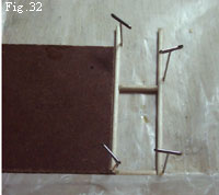
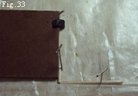
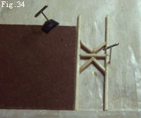
Cut the two vertical struts to the length shown on the plans and pin against a square corner on wax paper with the two axle-length pieces separating them. Position the center piece at the distance from the end of the struts shown on the plans. (Fig. 32.) Glue the center piece only to the struts. Break a short piece of dowel (do not separate), position against a square edge (Fig. 33) and glue. Make two of these for each side. Cut the legs of the right angle pieces to fit between the struts on either side of the horizontal piece and glue in place (Fig. 34.)
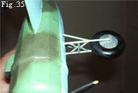
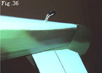
Paint the assembly and glue to the axles. After the model is completely assembled, drill 1/16" holes at the appropriate locations in the material behind N-3 on the underside of the cowl and insert the struts to the proper depth and alignment. Glue. For each gear, cut two pieces of dowel to the dimensions on the plans for the support struts. Glue them in place and paint. (Fig. 35.) The tail wheel is a circle of 1/16 with two pieces of soft wire glued to either side, shaped per plan and glued in a hole behind F-11. (Fig. 36.)
COWL FLAPS
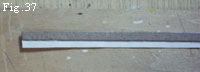
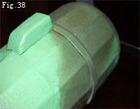
The cowl flaps were formed by cutting a strip of printer paper ¼" wide and a strip of cardboard from a writing tablet back 1/8" wide. Glue the cardboard strip to one half of the paper strip (Fig. 37.) Wrap the strip around the nacelle with the cardboard down and facing to the rear. Trim the ends to meet with no gap and glue in place, smoothing the paper down towards the front and sealing it to the covering. (Fig. 38.)
Additional NOTES
This was the first balsa and tissue model I've built using cyanoacrylate glue as the primary adhesive rather than Testors Model Cement. It does save a lot of time but can be a pain to work with. Debonder was a life-saver on more than one occasion! Accelerator was also very handy to instantly cure an application that was too heavy to cure itself quickly.
I also tried the UHU Stic a stick form of glue as an alternate to white glue for installing tissue. I still think the white glue (50/50 dilute with water) is much easier to work with because it dries slowly and allows ample time to position the tissue. In addition, joints can be smoothed with a wet finger.
The one great surprise was my first use of Canopy Glue. Not only did it not cloud the canopy material but it was a great bonding agent for almost anything, and it cures nearly instantly with the application of a heat gun.